Difference between revisions of "Video Cable"
Stephen Shaw (talk | contribs) (correct case on link) |
m (→PAL Video Output: typo) |
||
| (One intermediate revision by the same user not shown) | |||
| Line 63: | Line 63: | ||
The sixth pin being in the centre. | The sixth pin being in the centre. | ||
sound o o + | sound o o + 12V | ||
o earth | o earth | ||
b-y o o vid ( | b-y o o vid (luminance) | ||
o r-y | o r-y | ||
| Line 75: | Line 75: | ||
TI did not use RBG output in Europe so obtaining colour on a colour monitor from a European console is not easy but is possible with additional complex circuitry. A monitor with a "colour difference" input may work but do check impedances. | TI did not use RBG output in Europe so obtaining colour on a colour monitor from a European console is not easy but is possible with additional complex circuitry. A monitor with a "colour difference" input may work but do check impedances. | ||
[[Category:Hardware]] | |||
Latest revision as of 22:42, 5 November 2015
IMPORTANT: This main article refers to an NTSC TI-99/4a console. The European model used a different 6 pin plug. For details please see the end of the page.
These are instructions for making a video cable to replace the RF Modulator that came with the computer. Whereas the RF Modulator connected to the antenna leads of a TV, this cable will connect to the RCA audio/video connections of newer TVs, VCRs, PCs, etc. *
Parts List
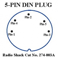
- 5-Pin DIN Plug (Radio Shack Cat No. 274-003A)
- Set of RCA type connectors (one for video and one for audio)
- Solder (use a fine electronics grade solder, NOT the plumbers type)
- Soldering iron (30W seems to work well for me)
- Wire strippers
- Diagonal cutting pliers
- Ohm Meter (for testing the cable)
- Some type of clamping device (to hold the plug still while you solder it)
What To Do
- Cut the RCA connectors off of one end of the RCA cable. This will expose the wires for us to work with and leave a set of RCA connectors on the opposite end.
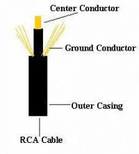
- Strip 1/2 inch of the outer casing away, exposing the center conductor surrounded by the grounding conductors.
- Cut away about half of the grounding conductors so as to decrease their quantity and enable us to fit them in the DIN plug.
- Strip away about 1/4 inch of the insulation on the center conductor.
- Repeat steps 2 to 4 on the other cable.
- Tin the center conductors of both cables (apply a thin covering of solder to the. This will make it easier to join the conductors to the plug.
- Twist the ground wires from both cables together and tin them also.
- You should have three wires to work with, a ground and two center conductors.
- Cut the tips of all the wires to make a clean and even connection.
Connecting The Wires
You must use caution when applying heat to the pins as the plastic holding the pin will melt if it gets too hot.
- Apply a small amount of solder to the inside of pins 2, 3, and 4.
- Heat pin-3 until the solder melts and insert one of the center conductors, remove the soldering iron and allow to cool.
- Repeat step 2 for pin 4
- When connecting to pin 2, you will use the ground wire not the center conductor
- Pin-1: Unused
- Pin-2: Ground Connection
- Pin-3: Audio Connection
- Pin-4: Video Connection
- Pin-5: Unused
Testing The Connection
- Use an Ohm meter to test the continuity between the pin and the other end of the cable. If you do not get a reading, then one of the connections is bad. Check the connection and reapply solder if needed.
- The things to check for are that you have continuity between the grounds on both RCA cables and pin-2 and that the center conductors have continuity from pins 3 and 4 to the respective RCA pins. You also want to ensure that none of the pins are shorting to any other pin.
Information on this page is from http: //www.nwlink.com/~theraven/ti994a/dinplug.htm, which is no longer available
PAL Video Output
In Europe a different video output (YUV) was used to connect to an external PAL-G modulator. This used a 6 pin DIN socket. The sixth pin being in the centre.
     sound  o             o + 12V
                  o earth
         b-y  o        o vid (luminance)
                  o r-y
The connection for a monochrome monitor should be across pin 6 (earth), and pin 2 (video). The video is monochrome, colour is obtained using the colour difference signals.
Beware of earthing pin 3 (r-y) to ground which can damage the video output I.C.
The input impedance of the monochrome monitor should be fairly high (above 560 ohms) and not 75 ohms (which is a standard value), as the video output circuit of the console can be damaged feeding a 75 ohm load.
TI did not use RBG output in Europe so obtaining colour on a colour monitor from a European console is not easy but is possible with additional complex circuitry. A monitor with a "colour difference" input may work but do check impedances.

